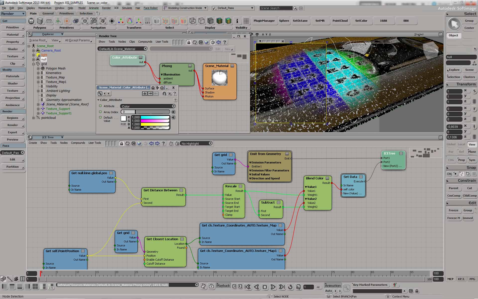
Here’s a question that came up on si-community awhile ago. How do I copy vertex attributes to the corresponding polygons?
This answer is the companion to this polygon-to-vertices post. I basically do the same thing, but in the opposite direction.


Here’s a question that came up on si-community awhile ago. How do I copy vertex attributes to the corresponding polygons?
This answer is the companion to this polygon-to-vertices post. I basically do the same thing, but in the opposite direction.
StrandPosition is an array of arrays: one array of positions for each strand.
Here’s a Python snippet:
from win32com.client import constants
xsi = Application

def dispFix( badDispatch ):
    import win32com.client.dynamic
    # Re-Wraps a bad dispatch into a working one:
    return win32com.client.dynamic.Dispatch(badDispatch)

attr = xsi.Selection(0).ActivePrimitive.Geometry.ICEAttributes( "StrandPosition" )
dataType = attr.DataType
data2D = attr.DataArray2D
for data in data2D:
   for elem in data:
      elem = dispFix(elem)
      xsi.LogMessage( "Vector3: " + str(elem.X) + ":" + str(elem.Y) + ":" + str(elem.Z) )
And here’s a JScript snippet:
a = Selection(0).ActivePrimitive.Geometry.ICEAttributes( "StrandPosition" );
LogMessage( ClassName(a) );

x = a.DataArray2D.toArray();
LogMessage( x.length );
for ( var i = 0; i < x.length; i++ )
{
   y = x[i].toArray();
   LogMessage( "=======================" );
   for ( var j = 0; j < y.length; j++ )
   {
      LogMessage( y[j].X + ", " + y[j].Y + ", " + y[j].Z );
   }
}
Here’s the basic recipe for troubleshooting a startup crash:
See also:
Rendering Vector
by olivier jeannel
Curve Retopo
by Land-Y

More fur additions
Compression Matting on fur controlled by texture map
Athens Tech Demo Siggraph 2013
Rigging Technical Reel made using Softimage at One Animation
ICE nodes have ports, and the ports have parameters. It’s the parameters that you work with in an ICE node PPG.
For simple types such as float, integer and boolean, you can access the port parameter value through ICENodeInputPort.Value. However, for more complex types, like a 3D vector, you need to go through the ICENodeInputPort.Parameters.
In either case (simple or complex types), to get an Fcurve, you get a parameter and then use Parameter.Source.
For example, suppose you have a Scalar node:
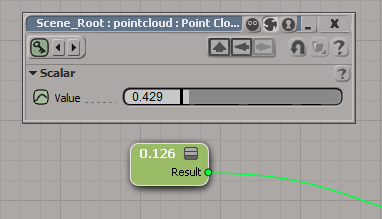
To get the value from a Scalar node, you’d do this:
si = Application
node = si.Dictionary.GetObject( "pointcloud.pointcloud.ICETree.ScalarNode" )
port = node.InputPorts(0)

# For scalars, you can just use the port.Value property
print port.Value

# Or you could go through the Parameters
print port.Parameters(0).Value
# 0.428628623486
# 0.428628623486

# It's a little confusing because the port and the parameter have the same name:
print port.FullName
print port.Parameters(0).FullName
# pointcloud.pointcloud.ICETree.ScalarNode.value
# pointcloud.pointcloud.ICETree.ScalarNode.value


# Now get the Fcurve
fcv = param.Source
Now consider the case of a 3D Vector node, where you have one port (value) and three parameters (value_x, value_y, and value_z):

In this case, you cannot use ICENodeInputPort.Value, so you have to go through the parameters collection:
si = Application
node = si.Dictionary.GetObject( "pointcloud.pointcloud.ICETree.3DVectorNode" )
port = node.InputPorts(0)
print port.FullName # pointcloud.pointcloud.ICETree.3DVectorNode.value
param = port.Parameters( 0 )
print param.FullName # pointcloud.pointcloud.ICETree.3DVectorNode.value_x
print param.Value # 0.933080613613

# Now get the Fcurve
fcv = param.Source
hat tip: Alan Fregtman
Here’s one way, using the not operator.
si = Application
si.SetUserPref( "SI3D_CONSTRAINT_COMPENSATION_MODE", not si.GetUserPref("SI3D_CONSTRAINT_COMPENSATION_MODE") )
The “problem” with this approach is that you’re toggling between 0 and -1, not between 0 and 1 (when you click the CnsComp button in the UI, you set the pref to either 0 or 1). The -1 happens because not 0 is -1.
Application.LogMessage( True == 1 )
Application.LogMessage( False == 0 )
Application.LogMessage( not False == -1 )
# INFO : True
# INFO : True
# INFO : True
So here’s a couple of other ways to toggle the preference value:
si = Application
si.SetUserPref( "SI3D_CONSTRAINT_COMPENSATION_MODE", 0 if si.GetUserPref("SI3D_CONSTRAINT_COMPENSATION_MODE") else 1 )
si = Application
toggle = [1,0]
si.SetUserPref( "SI3D_CONSTRAINT_COMPENSATION_MODE", toggle[si.GetUserPref("SI3D_CONSTRAINT_COMPENSATION_MODE")] )
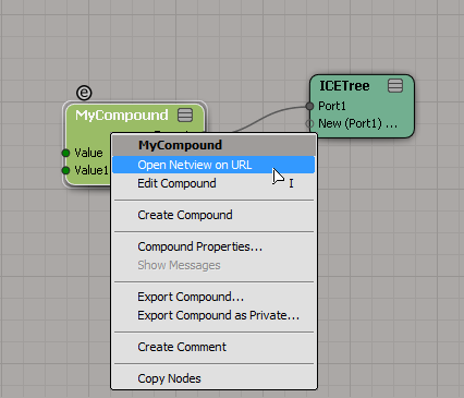
The short answer is that you can’t do it, not really. The best you can do is provide a URL in the compound properties
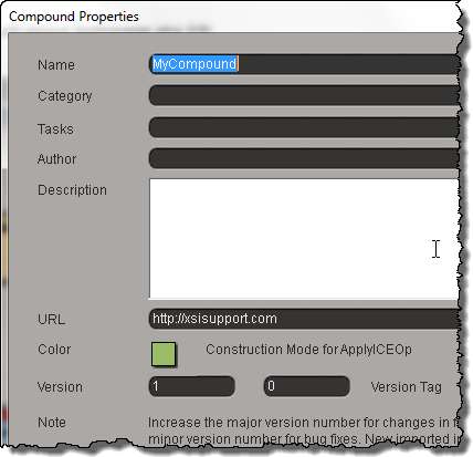
and then right-click the compound and click Open Netview on URL.
For ICE compounds, a CompoundNode property is loaded into the PPG when you inspect the compound.

This CompoundNode is like a proxy container for the actual compound, and it takes care of populating the PPG with the required controls, and finding the right help page. To do that, it just takes the name of the compound and constructs a URL like http://download.autodesk.com/global/docs/softimage2014/en_us/userguide/files/iceref_MyCompound.htm. (Hmm, having just said that, I figure if you had a local version of the help, then you could stick your own help page there, and Softimage would find it.)
For shader compounds it’s a little better, because you can put something like this in your PPG Logic, and it will work.
#ppg logic start
from win32com.client import constants

def OnInit():
    Application.LogMessage( "OnInit" )
    PPG.PPGLayout.SetAttribute( constants.siUIHelpFile, "http://lmgtfy.ca" )
#ppg logic end
hat tip: everybody on this thread
Arnold shader “OSO” in emTools version 1.910
by Mootzoid

A script that applies fur via ICE. And Compression Matting on the fur
feathers and script improvements
Compression Matting on fur controlled by texture map
UV to position
by Mathaeus
Transform UVs in the render tree
by NNois

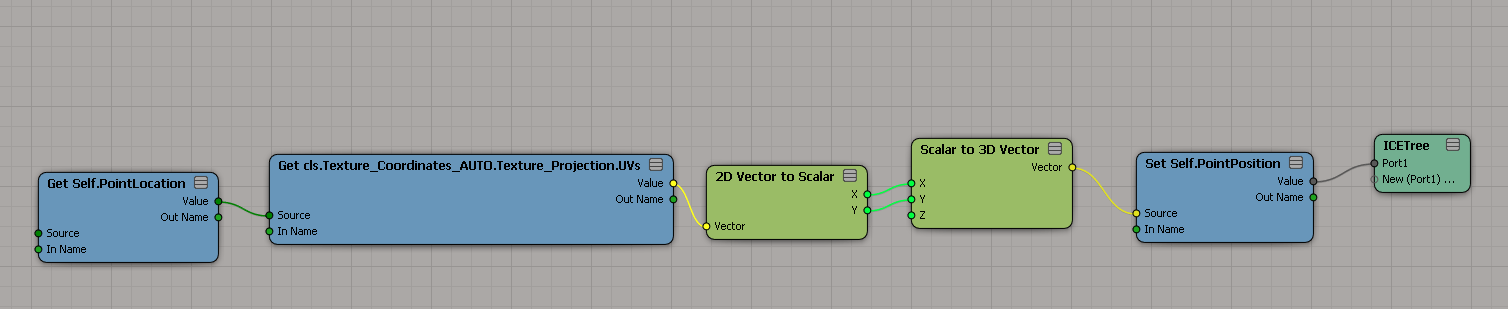
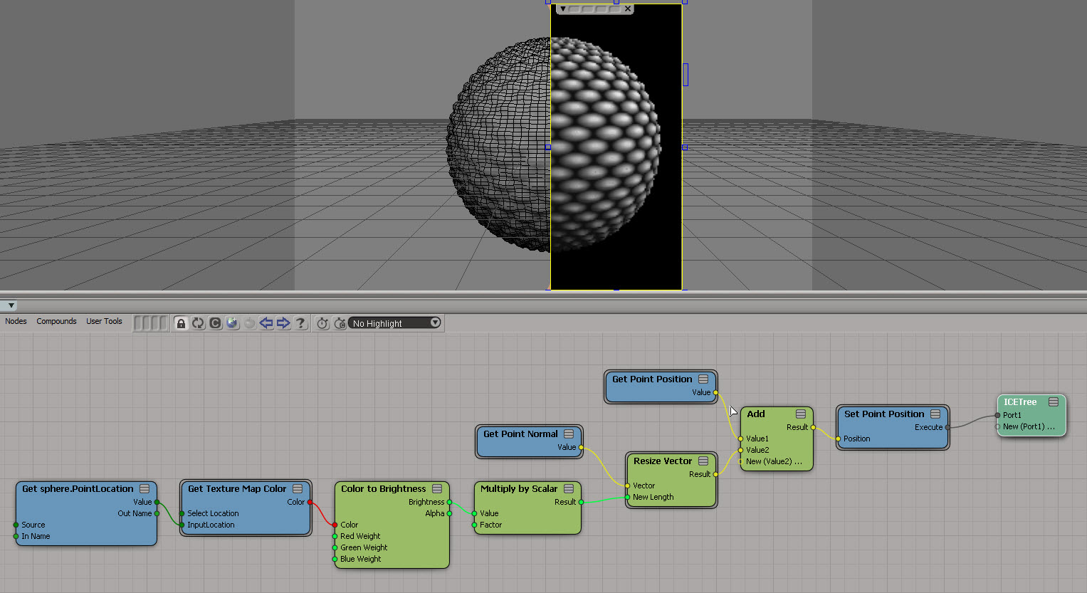
SOFTIMAGE|3D had a Effect > GC_Displace command (written with the C++ GDK) that displaced the vertices of a polygon mesh object based on an applied texture map. Using GC_Displace, you could “sculpt a terrain, a craggy moon surface, or even a face.”

I came across a screenshot of GC_Displace the other day, so for fun I re-created the basic effect in ICE:
Here’s a scripting question from the mailing list:
Why do I get “None” when I print ChainRoot.Children and
ChainRoot.Bones?si = Application chainRoot = si.Create2DSkeleton(0, 0, 0, 10, 0, 0, -90, 0, 0, 4) print chainRoot print chainRoot.Children # Not working print chainRoot.Bones # Not working print chainRoot.Effector # root1 # None # None # eff1
The answer is that ChainRoot.Children and ChainRoot.Bones are objects that don’t have a default property, so (in Python) you get the string representation of those objects, which is “None”.
ChainRoot and ChainRoot.Effector, being types of SIObject, and they do have a default property: the Name property.
ChainRoot.Children is an X3DObjectCollection, and ChainRoot.Bones is a ChainBoneCollection, and for whatever reason, those two collections don’t have Item as their default property (for some collections, like ISIVTCollection and LinktabRuleCollection, the Item property is the default property).
So the above Python is equivalent to this:
si = Application
chainRoot = si.Create2DSkeleton(0, 0, 0, 10, 0, 0, -90, 0, 0, 4)

print chainRoot.Name
print str( chainRoot.Children )
print chainRoot.Bones.__str__()
print chainRoot.Effector.Name

# root1
# None
# None
# eff1
Note that in JScript and VBScript, you’d get a “Type mismatch” error instead of the string “None” (in the original snippet).